
* FROM THE CONTENT OF SUCH FIRMWARE AND/OR THE USE MADE BY CUSTOMERS OF THE * DIRECT, INDIRECT OR CONSEQUENTIAL DAMAGES WITH RESPECT TO ANY CLAIMS ARISING AS A RESULT, QD electronic SHALL NOT BE HELD LIABLE FOR ANY * WITH CODING INFORMATION REGARDING THEIR PRODUCTS IN ORDER FOR THEM TO SAVE * THE PRESENT FIRMWARE WHICH IS FOR GUIDANCE ONLY AIMS AT PROVIDING CUSTOMERS Remember to set the pins to suit your display module! CS DC/RS RESET SDI/MOSI SCK LED VCC GND **other pins can be defined by youself,for example **if you don't need to control the LED pin,you can set it to 3.3V and set the pin definition to -1. **the SDA pin and SCK pin is defined by the system and can't be modified. when using the BREAKOUT BOARD only and using these hardware spi lines to the LCD, This program is a demo of clearing screen to display black,white,red,green,blue.

This application does not rely on any libraries and it is for ILI9341 To do this, only a 3.3V regulator between 5V from FTDI and VCC to IC is needed to install.Ĭopy these two dependent_libraly (LCDWIKI_GUI,LCDWIKI_SPI) to ArduinoIDE sketchbook location folder On the other hand, if the IC working with 3.3V rather than 5V can be used, no need to think about Voltage difference.

If Logic Level Converter is used instead of registers, Schematic will be simple. In this tips, because Arduino UNO worked with 5V and TFT modules works with 3.3V, 2.2k and 3.3k Ohm registers were used as Voltage Divider registers. group_assignments_page Connecting TFT module(3.3V), 3216(working with 3.3V) and class FTDI board(5V) ¶ Voltage Devider Registers 

FT230XS is working with 1.8V, but IO voltage is set to 3.3V. If you need to supply 3.3V to your board, we need 3.3V regulator externally before connecting VCC of your IC. This means the power supplied from this FTDI board to your boards is 5V. May be used to power VCCIO.When VCC is 3V3 pin 8įT230XS’s VCC is connected 5V from USB and VCC of J2 serial. FT230XS ¶ Class USB-serialģV3 output at 50mA. When VCC is 3.3V, all signals from this board will be 3.3V. Seeed Xiao as DAPLink to burn bootloader the SAMD11 boardsĪTtin圓216 can work with both 5V and 3.3V supply.
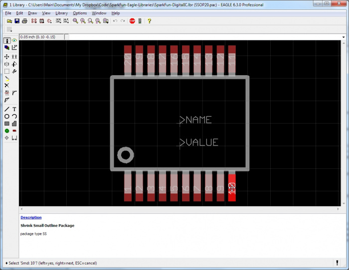
#FT230XS EAGLE LIBRARY CODE#
Video link path in mkdocs code and html tag
#FT230XS EAGLE LIBRARY HOW TO#
How to update local from remote repository (git pull -rebase)īurn Bootloader to SAMD11C with Microchip Studio (Windows) How to recover after rejected large files commit Xiao as SWD direct programmer for pre-burning Bootloader Principles and practices & Project managementĪrduino megaTinycore (working environment)Ĭonnecting TFT module(3.3V), 3216(working with 3.3V) and class FTDI board(5V)įA2022 USB-D11C-serial (Pi4 + Ubuntu + edbg + Xiao)įA2022 USB-D11C-serial (Ubuntu_Live_USB + edbg + Xiao) Invention, intellectual property and incomeġ.


 0 kommentar(er)
